LED Strip
Rotorflight drives up to 32 addressable WS2811/WS2812 LEDs from one data pin. Each LED can have its own colour and function: orientation lights, battery and arming warnings, or scale lighting -- navigation lights, anti-collision beacons, strobes and landing lights.
This guide sets up three scale lights. The LED Strip tab page explains every option.
Wiring
Each LED has four connections: 5 V, ground, data in and data out. The flight controller's LED pin goes to data in of the first LED; its data out goes to data in of the next, and so on.
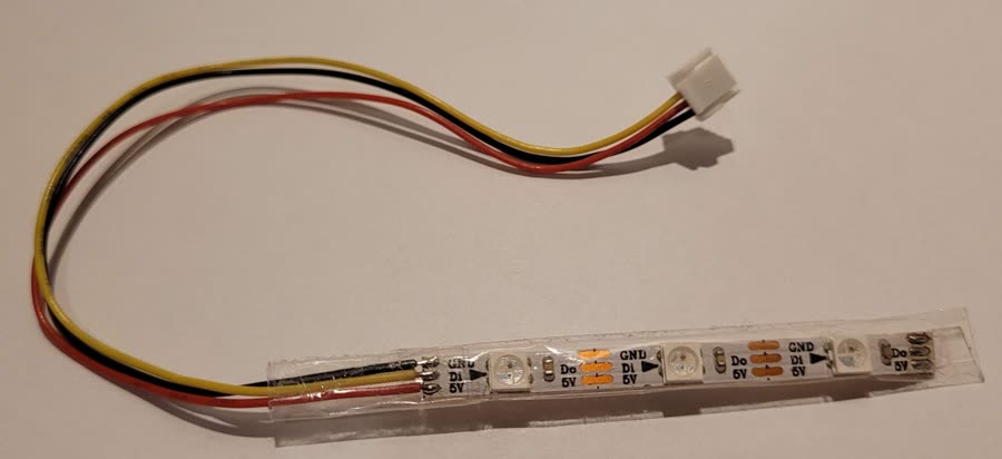
WS2812 strips (30, 60 or 144 LEDs per metre) are handy for testing and for lighting a boom. Individual 5 mm and 8 mm WS2811 LEDs suit scale lighting. With more than a few LEDs, power them from a separate 5 V supply.
The LED pin
The flight controller needs a pin assigned to LED_STRIP, with a timer and
DMA. Some boards have one; on others, repurpose a pin -- with the
Remap FC tab (2.4), or the CLI snippets
below.
Then turn on LED_STRIP under Features on the Configuration tab and Save and Reboot. The LED Strip tab appears.
Three scale lights
Place the LEDs
- On the LED Strip tab, switch to the wire-ordering mode.
- Click three squares on the grid, in turn. They're numbered 0, 1, 2 -- the order they're wired in.
- Give each the Color function. Save.
LED 0 -- green navigation light with strobe
- Select LED 0 and left-click green in the palette. It lights up.
- Turn on Blink with one tick: the LED briefly goes dark once per cycle.
- Right-click white: the dark moment becomes a white strobe flash.
If the LEDs are too bright, lower Overall brightness under LED Strip Global Settings.
LED 1 -- red anti-collision beacon
- Select LED 1, turn on Blink and tick a few adjacent steps.
- Right-click red. The LED flashes red.
LED 2 -- landing light
- Select LED 2, turn on Fade to alt color, and left-click white.
- Set the Profile to Status Alt: the LED dims. With Fade rate at 10 it fades slowly.
- To switch it from the radio, add an adjustment with LED Profile Selection on a switch: one position for Status (light on), one for Status Alt (light off).
Save.
A PicoBlade LED bus
For scale builds, a small bus of 4-pin Molex PicoBlade headers makes it easy to plug individual LEDs in and out.
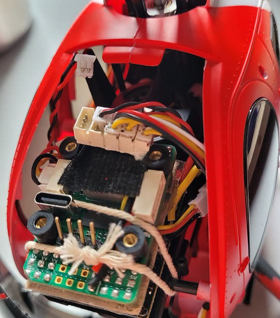
- Glue some 4-pin PicoBlade headers side by side.
- Bend the 5 V and ground pins to form two rails, and solder them.
- Bend each header's data out pin to the next header's data in pin, and solder.
- Wire 5 V, ground and data in to the flight controller, and insulate the underside with hot glue or epoxy.
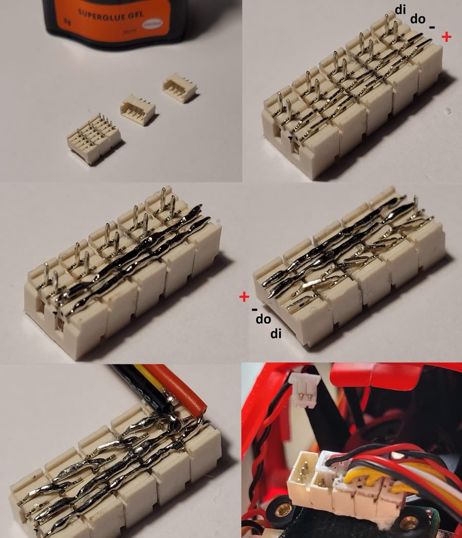
Ordinary (non-addressable) LEDs can go at the end of the bus, on 2-pin connectors.
Board snippets
CLI snippets to free a pin for the LED strip on some Rotorflight flight
controllers. Paste into the CLI; each ends
with save.
Port B's TX6 as the LED pin (RX6 keeps working):
resource SERIAL_TX 6 NONE
resource LED_STRIP 1 C07
timer C07 AF3
dma pin C07 0
save
Or RX6 instead: the same with SERIAL_RX 6 and pin C06.
The built-in status LED (pin B08) can't be chained, so move the LED strip to another pin. SCL:
resource I2C_SCL 1 NONE
resource LED_STRIP 1 B06
timer B06 AF2
dma pin B06 0
save
SDA works the same with I2C_SDA and pin B07. The RPM-S pin (5 V,
fine for a few LEDs) on V2 / V2.2:
resource LED_STRIP 1 A15
timer A15 AF1
dma pin A15 0
save
(V1: pin A08.)
The SBUS out pin. Strips usually need 5 V -- use port A or C's 5 V, not a higher BEC voltage.
resource SERIAL_RX 1 NONE
resource LED_STRIP 1 B07
timer B07 AF2
dma pin B07 0
feature LED_STRIP
save
The SBUS pin:
resource SERIAL_RX 2 NONE
resource LED_STRIP 1 A03
timer A03 AF2
dma pin A03 1
save